Camera effects have become a very normal part of daily social media or really any camera experience on the internet nowadays. With the whole pandemic situation, video calls have become way more popular, and to add a bit of artistic fun to the plain camera outputs, a lot of apps have integrated AR filters that overlay the face or change your background to hide that messy room.
With Spark AR Studio we can create such an experience that can not only be used on Instagram Stories or posts, but also on the video calls and live streams on these platforms. The best part is that it is so easy with a programming interface like the patch editor that the only limitation is your imagination.
This tutorial is the 4th part of the Instagram and Facebook AR series and will mainly focus on learning to create more complex effects using the patch editor and expects that you already know about different objects/assets and how to add or position them. For more detailed steps about basic functions, check out the previous parts:
- Creating Instagram and Facebook AR filters with Spark AR Studio — A beginner’s guide (Part 1)
- Creating Instagram and Facebook AR filters with Spark AR Studio (Part 2)
- Creating Instagram and Facebook AR Filters with Spark AR Studio (Part 3) — The Patch Editor (basic)
- Augmented Reality (AR) Development: Tools and Platforms
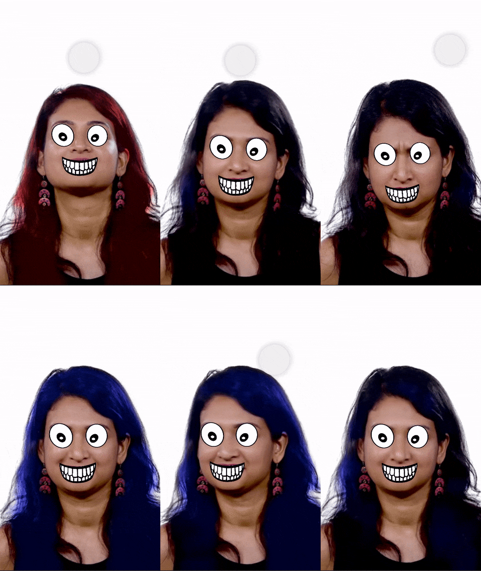
The effect I chose to create in this tutorial looks weird and funny, however, I chose this filter since its creation will cover several types of patches available in the patch editor. This will help you understand how the logic is connected with other elements of the effect we are creating so that you can understand the basics and build upon them to create more complex effects.
Before we start with the project, let us discuss what is happening in the effect. Firstly, the hair color toggled between red and blue by tapping on the screen. Then we have cartoonish eyes and mouth on the user’s face that move around with the user’s movement. Lastly, the texture for both the eyes and the mouth change when they are in a closed or open position. Now, let us understand how to implement all of these things!
Step 1:
Open the latest version (v. 105.1 at the time of writing) of Spark AR studio. If you don’t have it installed, you can get it here.
Step 2:
Start a new project using the ‘Hair Color’ template on the ‘Create New’ screen.
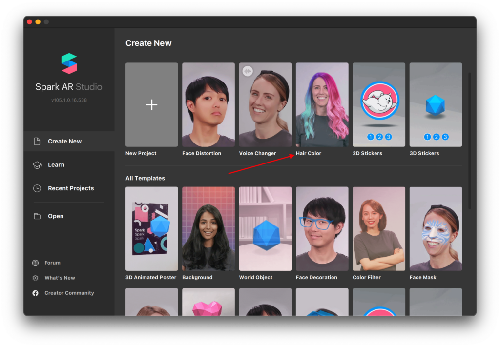
Hair segmentation is relatively new to Spark AR and to make it easy to use it in projects, Spark provides us with this template to give us a jumpstart!
Step 3:
In previous parts of this tutorial series (linked at the top), we have already learned about the Spark AR interface, objects, materials, textures, and the different editor panels.
Now, in this ‘Hair Color’ template, after following the steps on the pop-ups, you will be able to get to the inspector panel on the right and be able to edit the colors of hair very easily. You can play around with these options to see what they do, but if you want to see how this is working, you can make the patch editor visible from the options at the top (View > show/hide patch editor).
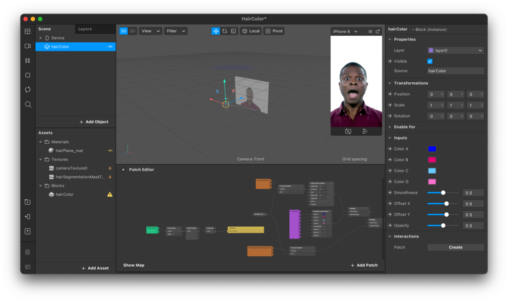
To make things simple Spark AR has already done all the heavy lifting of using shaders, forehead tracking, and other complex patches to make this possible.
Let’s come back to the hair color part of our effect later and group together all the patches related to it so it does not bother us. You can do this by selecting all the patches by dragging over them and then right-clicking and selecting the group. You can also use the shortcut Ctrl/cmd + G. Name this group ‘hair color’ so we know what it represents. We can always expand this group by clicking on the outward pointing arrows.

Step 4:
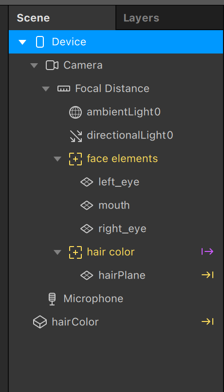
Let’s start by adding the objects for our eyes and mouth images to the scene panel. We will use the ‘plane’ objects to represent these elements and add them inside a ‘face tracker’ so everything is aligned with the user’s face. You can refer to Part 2 of this series to learn more about planes.
Notice that there is already a ‘face tracker’ in this template, but that one is being used for the hair color so we can ignore it and create a separate one. You may consider renaming to avoid confusion. Add the objects in the following manner:
Step 5:
Next, we need to create materials for those planes and assign the images to them. You can download the assets I used from here. Set all the material’s shader types to ‘flat’ so no light affects their visibility. Learn more about materials in Part 1. Also, set the compression for all the texture assets to ‘no compression.’
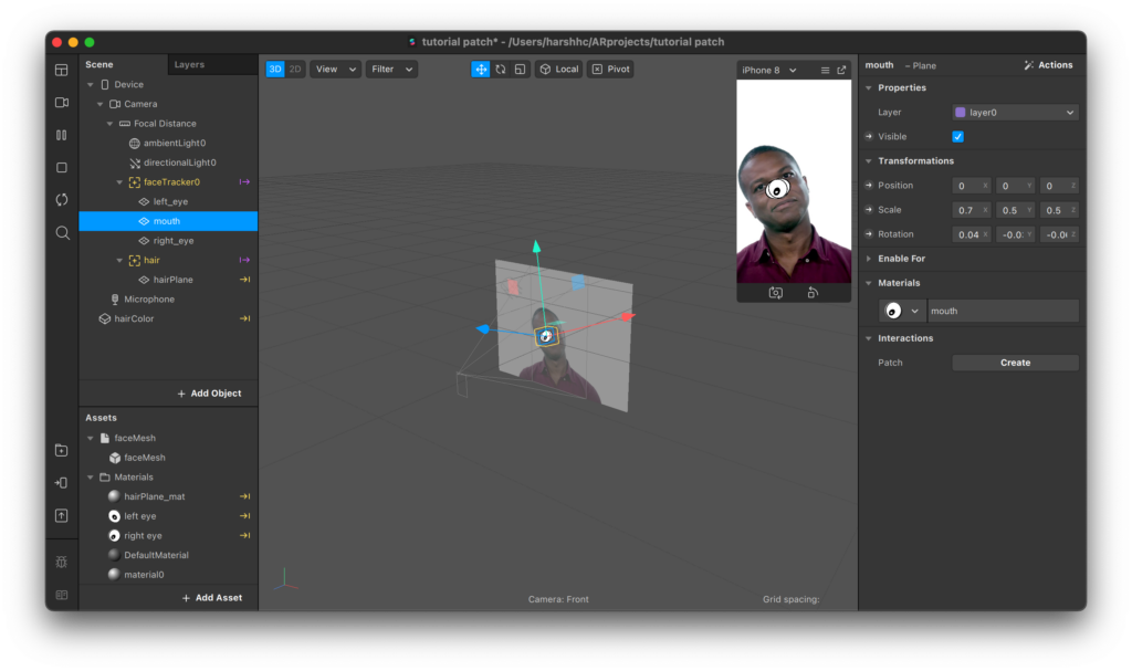
After adding all the images, set the scale property of the eye planes to 0.5 for all x,y, and z-axis. For the mouth plane set the x value to 0.7 and 0.5 for the others.
You should have something looking like this by now:
Step 6:
Now we’re done with the setup and it’s finally time to dive into the patch editor.
First, we will give each plane the correct positions. In the patch editor, double click/right-click to open up the patch search window. The best part about the patch editor is that it is really intuitive and all the documentation is provided right there for reference on the go.
As you can see from the options on the left, select the ‘Face Landmarks’ category and add the patch for ‘Eyeball.’ You can always search for what you’re looking for straight away to find it faster.
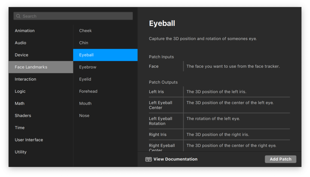
As you can see from the reference docs on the right, the Eyeball patch will provide us with the location for both the 3D left and right iris along with their rotation and center points. For the input to this patch, we will need to provide the face from the face tracker.
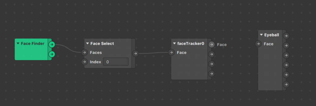
So let’s add the face tracker group of patches next to get the value of ‘face’ that we need to send to the eyeball patch. We can do this by simply dragging our face tracker from the scene panel to the patch editor.
Step 7:
As you can already guess, we need to drag and connect the face output value from the faceTracker0 patch to the input value for Eyeball.
Once this is done, we need a way to set the position properties of our eye planes. To access and set a property of an object in the patch editor, we need to select the object and then, from the inspector panel, we need to click on the small arrow on the right of the property we want to import. In our case, it is the 3D position and rotation for both planes.
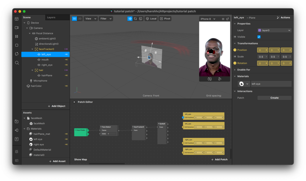
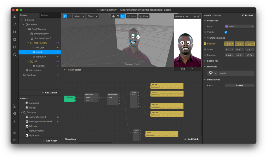
Now, to put those planes in the right position and rotation, just connect the right nodes together, as seen below.

Step 8:
The eyes are now looking good. For the mouth, we need to follow a similar method and use the mouth landmark patch instead.
For this patch, it expects the same face input however, for the outputs, we don’t have access to the center of the mouth so we’ll have to adjust the position of the plane to the center of the lower or upper lip. We also don’t have the rotation but we can ignore that since the mouth plane will inherit it from the face tracker.
The face now looks a bit creepy, but at least everything’s in the correct position!
Step 9:
It is time to bring some interactivity to our effect! We can implement the interactions by looking at the ‘Interaction’ category in the patch search window.
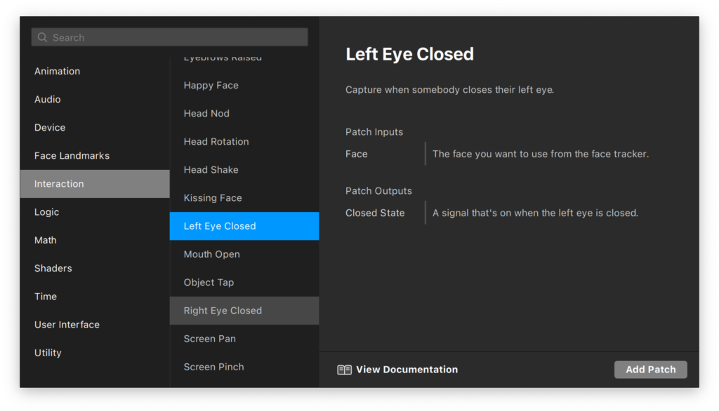
Here you will find plenty of interactions that can help you create a wide variety of effects. For this particular one, we’re interested in the ‘Left Eye Closed,’ ‘Right Eye Closed,’ and the ‘Mouth Open’ patch. It is always a good idea to take note of the input and output types mentioned in the reference on the right while adding the patches.
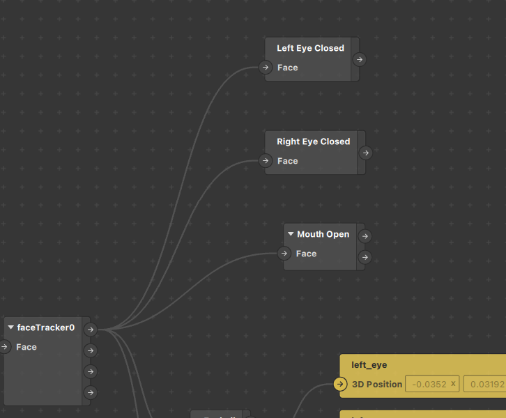
All of the patches we just added take in the same input — the face from the face tracker — so just connect the nodes together like this:
Step 10:
If you take a look at the outputs for these patches, you’ll notice they give out a boolean value (true or false) which is represented as a checkbox in Spark AR. If you want to find the output value type, you can just click on the output arrow of the node.
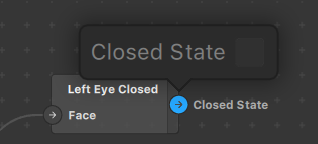
Since the output is boolean, we will need to set the texture of the materials for the left eye, right eye, and mouth to the open or closed image depending on the output value.
We need to add a conditional statement to implement this correctly. If you have done some programming before then you can understand better, however it is fairly straightforward. From the patch search window, add the ‘If Then Else’ patch from the ‘Logic’ category. Add three of these patches for each element.
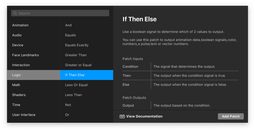
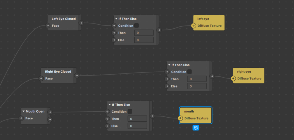
For the condition input, we’re simply going to pass in the output from the interaction patches. Since this patch will decide which texture to show on the materials, the output is going to set the ‘texture’ property of the eyes’s and mouth’s material. Import these properties like you did for the 3D position of the planes. You can access it by simply selecting the material and then the arrow beside the property in the inspector panel.
Your arrangement should look somewhat like this:
Step 11:
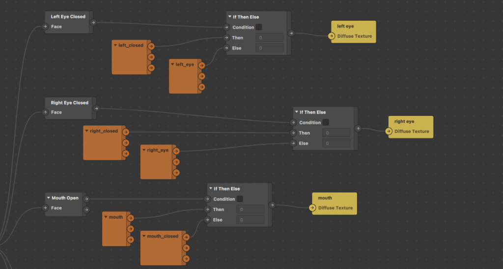
For the inputs for then and else nodes, we need to pass in the textures themselves. You can drag and drop these textures from the asset panel and Spark AR will automatically create patch instances for you.
You can pass in these textures as inputs by connecting the ‘rgba’ output node to the correct nodes in the if/else patch. The logic behind this arrangement translated in plain English would be: If the left eye is closed, then show the ‘left eye closed’ texture, otherwise show the ‘left eye open’ texture. The logic is the same for the right eye and mouth.
Step 12:
Our eyes and mouth are now nearly complete. There is just a small bug we need to fix. You may have noticed that when the mouth is opened the texture changes, however, it seems as though it is not in the right position. This happens because we have set its position to match the lower lip center face landmark, however, the mouth open texture is a bit bigger and needs to be shifted upwards to make it appear in the correct position.
We can fix this by adding another ‘if then else’ statement that adds a value of 0.02 units to the y position to the lower lip landmark if the mouth is open or otherwise add 0, which is then set to the mouth plane object’s 3D position.
This may seem a little overwhelming, but really isn’t that hard. Note: You can set the value to whatever you wish, I used 0.02 since that value fits perfectly in my case.
To implement this we will need to move some patches around so they are easier to connect. (This is the only shortcoming of visual-based programming interfaces, they may become crowded and hard to manage at times). The arrangement for this will look somewhat like the image below:
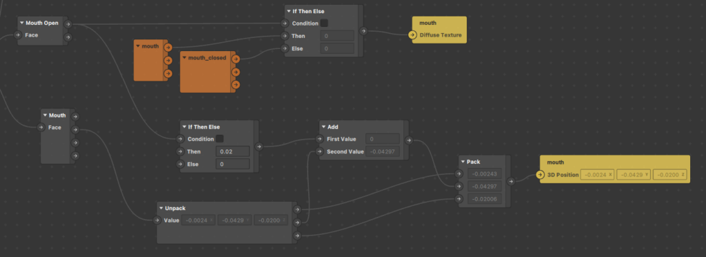
After moving all the mouth patches near each other, add two new patches called ‘Unpack’ and ‘Pack.’ The ‘unpack’ patch separates out the three axis vector values into individual numbers. These individual values can be optionally altered and then packed back together as a 3D vector value using the ‘Pack’ patch to send it as input to the 3D position of the mouth.
In this case, we altered the y axis value and added the output from the ‘if then else’ patch (0.02 or 0 depending on if the mouth is open or not) we added earlier.
Step 13:
We are now completely done with the facial elements. Now to learn another type of interaction in effects, this tutorial also covers how to change the color of the hair by tapping on the screen.
We can now group together all the patches for the facial expressions and then go back and expand the hair color group.
In the hair color patch group, you will be able to see a purple patch that is responsible for getting the values from the inspector panel for the gradient colors and actually setting it to the hair in the patches.
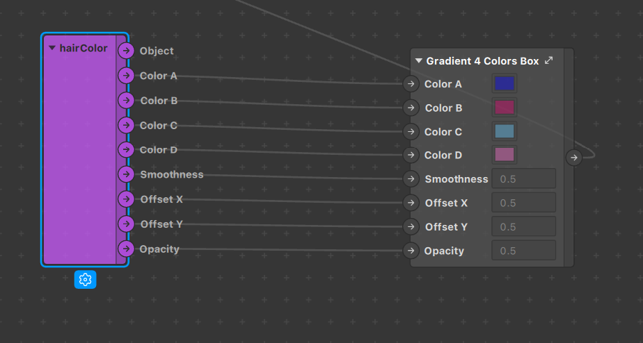
We will need to alter this part so we can set different colors based on screen taps. The first step will be to disconnect the four color connections between these patches so the color can no longer be altered from the inspector panel.
Once these are disconnected, we can start by adding the ‘Screen Tap’ patch found in the ‘Interaction’ category of the patch search window. You do not have to pass any specific input to this patch and the output is a pulse type. That means it fires off for a short period of time passing a boolean value whenever the screen tap event occurs.
Step 14:
Now we can define the different colors we want the hair to toggle between. To do this, add the ‘Option Picker’ patch in the ‘Utility’ category. Right-click on it and change the number of inputs to two (or whatever number you want) and then set the data type to ‘color’ by selecting it from the blue drop-down at the bottom of the patch. Click on the color boxes for the options and set the color to the ones you’d like to toggle between.
Next, since we no longer want a gradient on the hair, we can set the output value of this option picker to the input of all four color inputs in the Color box patch.
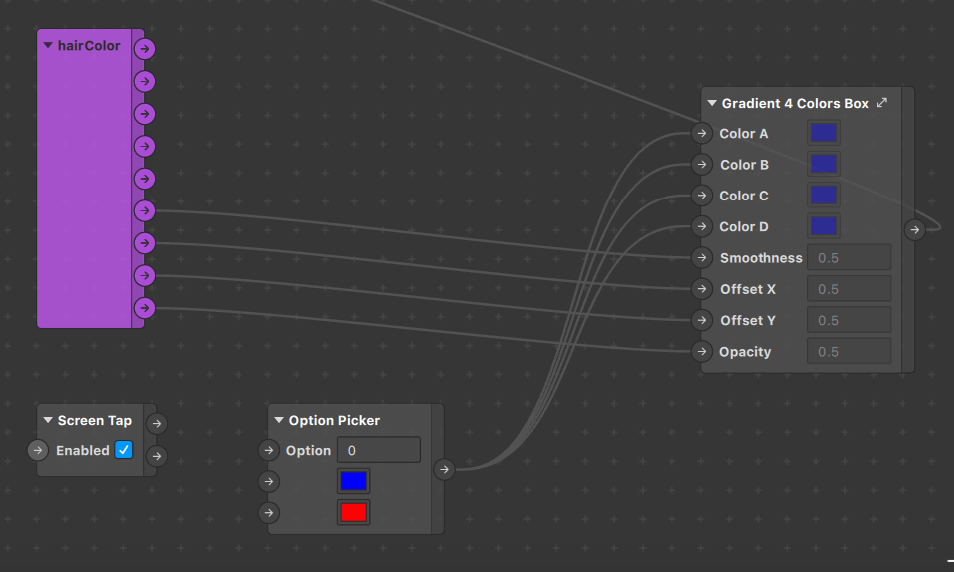
Step 15:
Lastly, we need a way to switch between all the options in the option picker. We can do this using the ‘Counter’ patch available under the ‘Utility’ category.
The counter patch takes in a pulse input to increase or decrease the current value and gives the current value count as the output. The output for this patch should serve as input to the option picker so we can change the options.
The output pulse from the screen tap patch can be used to increase the count for the Counter patch and the logic will be complete. Don’t forget to specify the range of the counter in the Counter patch so that it matches with the Option Picker. The complete arrangement will look like this:
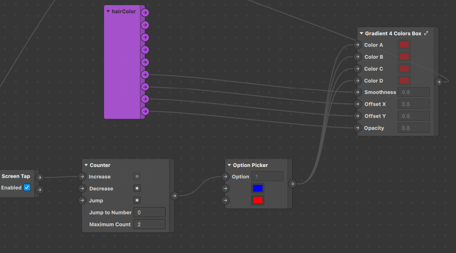
You can follow this guide to learn about testing the effect on your device and this one for publishing.
Conclusion
Congratulations on creating the effect! This tutorial covered all the most commonly used patches in the Spark AR Patch editor, thereby allowing you to use them to create more complex effects.
In the next part of this series, we will learn how to use 3D objects in our effects. Until then!

Comments 0 Responses