
A few months back, as I was browsing through some fascinating projects on Augmented Reality, I came across an extremely intriguing project, which was one of the most artistic applications of AR I could think of. The final effects of the app looked something like this:
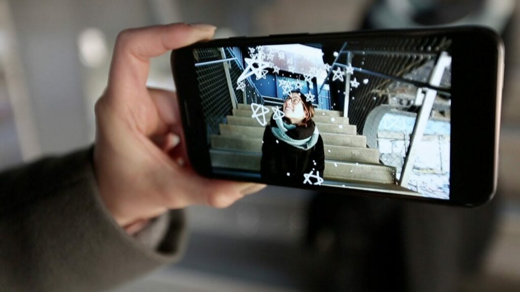
Cool isn’t it!? Go ahead and try out the awesome app for yourself.
After having thoroughly played around with the app, I decided to try and replicate the project to learn something new and have some fun. But I didn’t realize the extent of theoretical understanding I needed before even attempting the project.
Here are some of the most important concepts I had to learn and understand while attempting this project.
Coordinate Spaces in 3D Applications
In any 3D application, there are four main coordinate spaces:
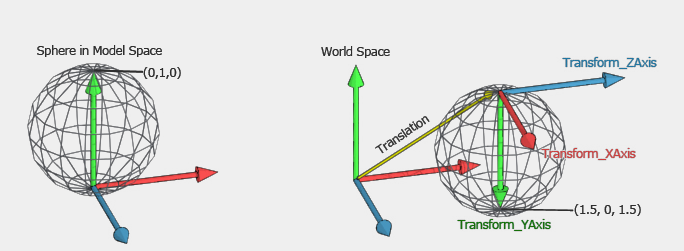
- Model Space: The model space is the space local to the objects. It describes the relative position of the points on the body of the object. These relative locations don’t change with a change in the location or orientation of the object in the world space.
- World Space: The world space describes the relative position of all the objects in your application. This includes the location as well as the orientation of all the objects relative to each other. All the physics calculations are performed on the world space coordinates.
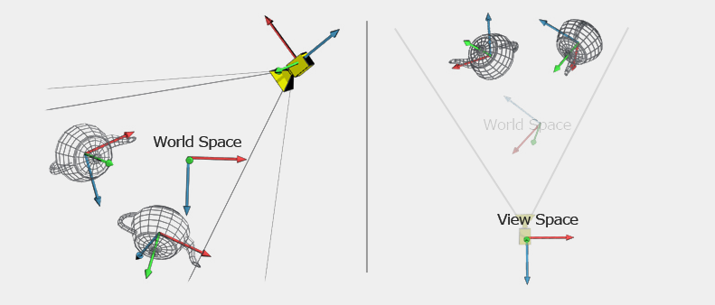
- View Space: The view space is also known as camera space. This is the coordinate system relative to the camera. In this space, the camera is at the position (0, 0, 0), and the direction of the camera is the z-axis of the coordinate system. We don’t need to render anything with a negative Z value, since it would be behind the camera.
- Screen Space: The screen space is the (X, Y) coordinate system of whatever screen you’re displaying your graphics on. In our case, this will represent the coordinated of the screen of the phone and all the user touches will be mapped onto this space.
Now, since there are multiple coordinate spaces, we need some way to transform coordinates from one space to another.
In computer graphics, the transformation from one space to another is done using a matrix. So when rendering the full scene, the following matrices are stored:
- Matrices corresponding to each object in the world space. These matrices represent the transformations of the local coordinates of the objects in the model space to the respective coordinates in the world space.
- One overall matrix for the view. This corresponds to the transformation from world space to view space. Note that you only need one of these, since it’s assumed that everything will be in world space before being transformed into view space.
- One overall matrix known as the Projection Matrix is saved in order to transform objects from view space into a space that’s ready for mapping into screen space.
Now that we understand the basics of coordinate spaces, the next step is to understand the principles involved in treating 2D lines as 3D.
Visualizing 2 Dimensional lines in 3 Dimensions
By itself, drawing a line is one of the simplest things you can do. Ironically, when we try to draw 2D lines in 3D, we encounter a number of problems:
- The lines have a 2D look, which means the width of lines does not depend on the distance from the camera view. Think of a simple 2D application and how the lines have the same thickness regardless of their location or viewpoint.
- The rendered lines are broken and not of customary thickness.
One of the ways to solve this problem is to represent each line segment as a set of triangles. Adjacent triangles (or quads) are drawn without any gaps between them. In this case, we have to deal with two problems:
- In 3D, a set of triangles looks like a ribbon, i.e., it may look like a solid line under certain views, but the appearance of a line is lost when the viewpoint is changed.
- The line width depends on the camera view.
To address problem 1, we have to make sure the geometry is always facing the camera, i.e., recompute the geometries every time the viewpoint is changed. For problem 2, the solution is similar — re-adjust the ribbon width with the change of viewport.

A very effective way to achieve the desired effect is to use GLSL shaders. The discussion on shaders is a supplementary part and is not used explicitly in the project, so I’ve added this as an Appendix at the end of this tutorial.
Line Smoothing
Another thing to remember is that after rendering the lines in this way, we need to smooth the line edges to improve the experience. Next, I’ll try to give a brief overview of how the smoothing process is being carried out.
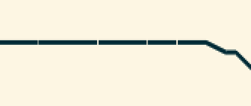
inTangent and outTangent
The rendering of lines in Unity is done in form of multiple Keyframes. The incoming tangent (or inTangent) affects the slope of the curve from the previous key to this key. The outgoing tangent (or outTangent) affects the slope of the curve from this key to the next key. The incoming tangent matches the incoming slope of the curve and the outgoing tangent matches the outgoing slope of the curve.
Line Smoothing using SmoothTangent
In our project, we are using a function AnimationCurve.SmoothTangent to smooth out the lines. What this function basically does is that it makes the inTangent and outTangent line up.The first parameter in the function is a weight. Using a weight of 0 will make the final smooth slope an average of what the inTangent and outTangent were before.
So this was the basic theory that was being implemented on the backend of this project.
Here, I present a step-by-step tutorial for making a simple and easy implementation of the above theory in Unity3D using a custom Unity Package named CurvedLineRenderer.
Making the app in Unity3D
In this section, I’ll be explaining the steps involved in making this project in Unity.
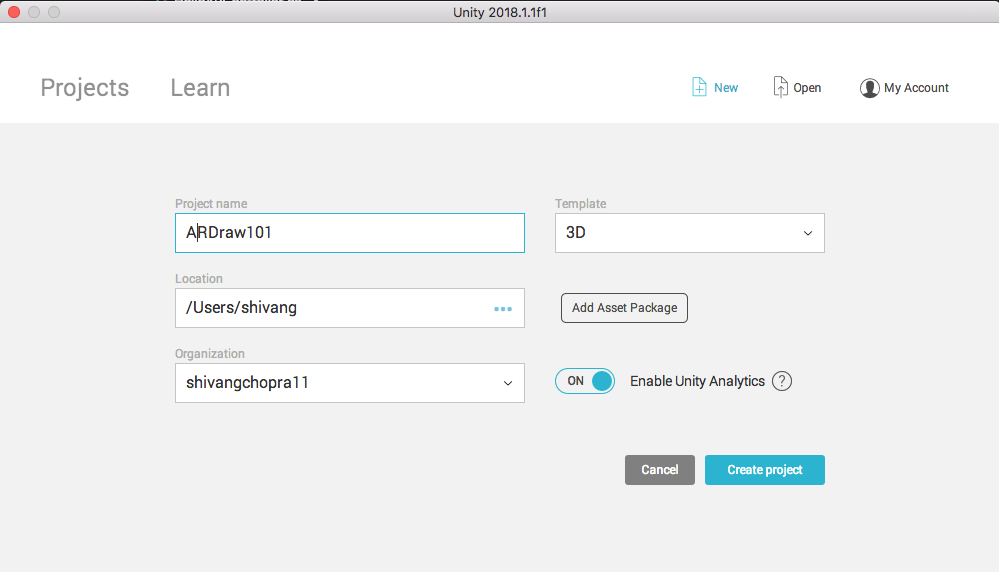
Step 1: Open Unity3D and create a new project named ARDraw101. Make sure to select 3D in the template section.
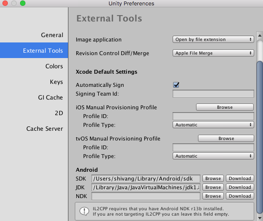
Step 2: After the project is created, head over to Unity->Unity Preferences->External Tools. Add the path of Android SDK and Android JDK taken from Android Studio into the respective fields.
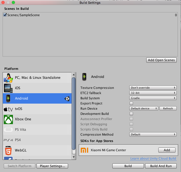
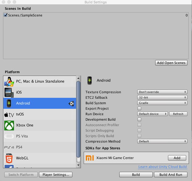
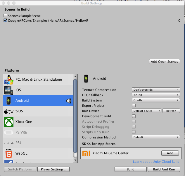
Step 3: Go to File->Build Setting and select Android in the Platforms list. Then click Switch Platform. The Unity logo should appear in front of Android in the platforms list.
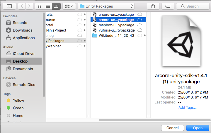
Step 4: Download the ARCore SDK for Unity from the following link:
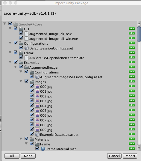
Step 5: Right click in the Assets window->Import Package->Custom Package and select the downloaded ARCore SDK.
Step 6: Click on All and then Import in the dialog box that appears.
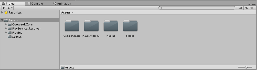
Step 7: The Project window should look like this.
Step 8: Go to File-> Build Settings and click on Player Settings.
Step 9: The following window will appear in the Inspector.
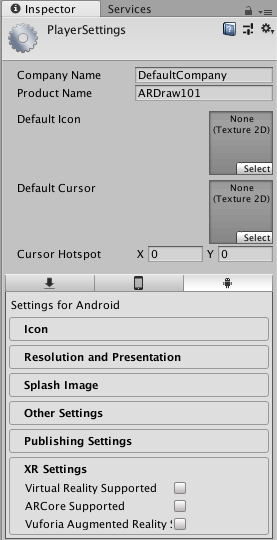
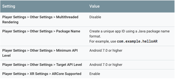
Step 10: In the Inspector window, configure the following settings except for Target API level, which should be set to Automatic (highest installed):
Step 11: Download and import the following package in Unity3D (similar to steps 5 and 6).
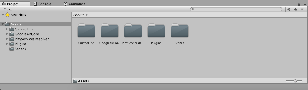
Step 12: The Project window should now look like this.
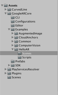
Step 13: Go to Assets->GoogleARCore->Examples->Scenes and open HelloAR scene.
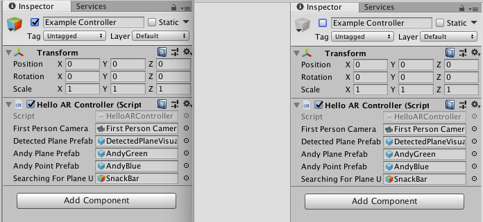
Step 14: Now, for the following gameObjects: Example Controller, Plane Generator, Point Cloud, and Canvas, click on each one of them, and in the Inspector window, disable each one of them by unchecking the check box next to the top cube as shown below. This is done because these are the default components for ground plane detection and raycasting in ARCore, which are not required for this project.
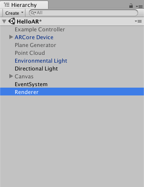
Step 15: Create an empty object in Hierarchy and name it Renderer. The Hierarchy window should now look something like this:
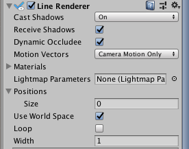
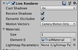
Step 16: Add the CurvedLineRenderer component to the Renderer GameObject. In the LineRenderer component, set the value of Positions->Size to 0.
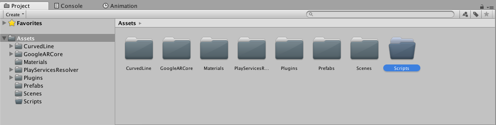
Step 17: In the Assets folder, create three new folders named Materials, Prefabs, and Scripts. The Project window should now look like this.
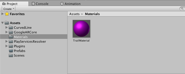
Step 18: Open the Materials folder and create a new material named TrailMaterial.
Step 19: Drag and drop this material into Renderer->LineRenderer->Material.
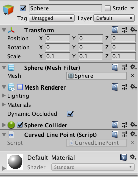
Step 20: Create a new Sphere in Hierarchy and rescale it to (0.1, 0.1, 0.1) in the Inspector window. Also add the Curved Line Point component to it and disable its MeshRenderer. The basic thing we’re doing here is instantiating new spheres at every touch and then rendering a line between consecutive spheres. When we disable the MeshRenderer, we see only the lines and not the spheres.
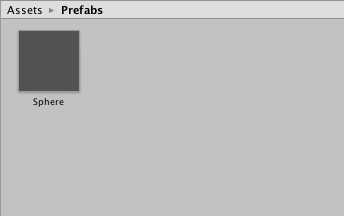
Step 21: Drag and drop this sphere in Prefabs folder to make it a Prefab and then delete the sphere.
Step 22: Go to the Scripts folder and create a new C# script named TrailScript. Open the script and paste the following code in it. Then add this script to the Renderer GameObject. Essentially, what this script is doing is instantiating a sphere at every touch and then rendering a line between all the spheres. Also, as the MeshRenderer of the sphere prefab is disabled, they are invisible in the final project. Then the spheres are set as children of FirstPersonCamera to anchor them in place.
using System.Collections;
using System.Collections.Generic;
using UnityEngine;
using GoogleARCore;
#if UNITY_EDITOR
    // Set up touch input propagation while using Instant Preview in the editor.
    using Input = GoogleARCore.InstantPreviewInput;
#endif


public class TrailScript : MonoBehaviour {

	public GameObject gameObject;
	public GameObject camera;
	public List Points = new List();

	// Use this for initialization
	void Start () {

	}

	// Update is called once per frame
	void Update () {

		if(Input.GetMouseButton(0) || Input.touchCount>0) {
			Debug.Log("Touched");
			Vector3 camPos = camera.transform.position;
 			Vector3 camDirection = camera.transform.forward;
 			Quaternion camRotation = camera.transform.rotation;
 			float spawnDistance = 2;
			Debug.Log("Touched"+camPos.x+" "+camPos.y+" "+camPos.z);
 			Vector3 spawnPos = camPos + (camDirection * spawnDistance);
			GameObject cur = Instantiate(gameObject, spawnPos,  camRotation);
			cur.transform.SetParent(this.transform);
		}
	}
}
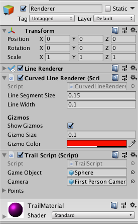
Step 23: In the TrailScript component of Renderer GameObject, drag and drop Prefabs->Sphere to Game Object and ARCoreDevice->First Person Camera to Camera.
Step 24: Go to File->Build Settings and click on add open scenes and uncheck Scenes/SampleScene.
Step 25: Finally, build the app by pressing Ctrl.(Cmd.) + B and test it out. The final result should be as follows:
For the repository of the above project, visit the following link:
That’s it! I hope you liked this post. If you did, don’t forget to 👏 and leave a comment 💬 below.
Next Up: Adding multiple lines in the same project and adding functionality for changing color and thickness of the rendered lines.
Discuss this post on Hacker News and Reddit
Want to have more fun building such apps, we at Coding Blocks are dedicated to teach cutting-edge technologies in simple and exciting ways. Check out our courses at https://codingblocks.com/
Appendix
Shaders
The various types of shaders and their respective purposes are discussed below.
Vertex shader
The vertex shader is what helps transform 3D world coordinates into screen coordinates. Simply speaking, this is where we deal with making sure lines always face the camera. In order to implement a vertex shader, we have to use a model-view-projection (MVP) matrix, which is the matrix updated on every view change.
The calculation of each vertex is done like this:
position = ModelViewProjectionMatrix * Vertex;
Geometry shader
The geometry shader’s main goal is to take each line segment and turn it into a strip of triangles that have enough filling on each side so that the consecutive line segment is connected without a gap. The position of each vertex of the triangle is calculated in relation to the viewport of the widget that displays the whole scene. This allows the lines to have a constant thickness despite their location in the 3D world.
Fragment shader
The fragment shader is a simple pass-through shader. It takes the incoming color and assigns it to each fragment.
After the shaders have been applied, there is still work that needs to be done on the lines in order to smoothen them and improve their texture.
Comments 0 Responses