OpenCV is a powerful tool for doing intensive operations in real-time, even for resource-limited mobile devices. Throughout a couple of tutorials, we’re going to create an Android app that applies various effects over images.
In part 1, horizontal and vertical image stitching is discussed to merge 2 or more images.
In part 2, the cartoon effect is applied to a single image.
This tutorial will discuss how to use OpenCV to make an image transparent by using the alpha channel. The sections covered in this tutorial are as follows:
- What is Alpha Channel?
- Working with Alpha Channel in OpenCV
- Image Blending
- Region Blending
- Building Android App
The source code for this tutorial is available in this GitHub project.
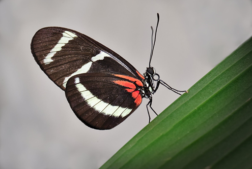
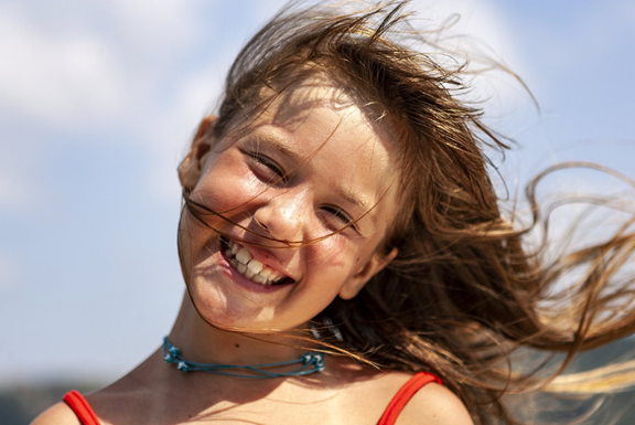
The 2 images given below will be used in our experiments. Let’s get started.
What is the Alpha Channel?
When an image is visualized, the values assigned to its color space channels are what control the appearance of its pixels. If each pixel is represented as an 8-bit channel, then the range of the pixel values is from 0 to 255, where 0 means no color and 255 means full color.
For a color space such as RGB, there are 3 channels—red, green, and blue. If a color is to be assigned to a pixel using RGB, then all you need to do is just specify the values of the 3 channels. For example, if the pure red color is to be represented using the RGB color space, then the red channel will be assigned the highest possible value, and the other 2 channels the lowest possible values. Thus, the values for the red, green, and blue channels will be 255, 0, and 0 respectively.
Besides specifying the values for each channel of the color space, there’s another factor that controls how the color appears on the screen—pixel transparency, which allows you to control whether the pixel is to be transparent or not. We do this using a new channel added to the color space named alpha.
For making the RGB colors transparent, a fourth channel is added, representing the alpha channel. This channel has the same size (rows and columns) as all other channels. Its values are assigned the same way that values for the other channels are assigned. That is, if each pixel is represented as 8-bit, then the values for the alpha channel range from 0 to 255.
We know that the 0 value for any of the RGB channels means no color (black) and 255 means full color (white). For the alpha channel, what do values 0 and 255 represent? These values help calculate the fraction of pixel color that will appear on the screen, according to the equation below. This fraction is then multiplied by the pixel value to get the result.
When the alpha is 0, the fraction is also 0.0, and thus the old pixel value is multiplied by 0 to return 0. This means nothing from the pixel is taken, and thus the result is 100% transparent.
When the alpha is 255, the fraction will be 1.0, and thus the full value of the pixel is multiplied by 1.0 to return the same pixel value unchanged. This means no transparency at all.
As a summary, the 0 value for the alpha channel means that the pixel is 100% transparent. The alpha value 255 means the full pixel value is used unchanged and thus the result is not transparent at all. The pixel is more transparent when the alpha value approaches 0.
According to the above discussion, we know how to make an image transparent. This leaves us with a question. How is this useful? Let’s discuss one benefit—alpha blending or compositing.
Assume that there is no alpha channel at all and we need to add the color of the 2 pixels listed below:
- Pixel1 = (R1, G1, B1) = (200, 150, 100)
- Pixel2 = (R2, G2, B2) = (100, 250, 220)
The result of adding Pixel1 to Pixel2 is as follows:
If each channel is represented using 8 bits, then the channel values range from 0 to 255. The combined colors above exceed this range. When the channel value is outside the range (below 0 or above 255), it will be clipped to be inside the range.
Thus, the result of adding the above 2 pixels is: 255, 255, 255. Assuming that the result of adding most of the pixels in 2 images exceeds the range, then the output image will be nearly white, and thus the details in the 2 images are lost. To overcome this issue, we use the alpha channel.
When adding 2 pixels together while using the alpha channel, the value in the alpha channel specifies how much of the pixel contributes to the result of the addition. Let’s discuss this.
Assume that the alpha channel is added to the previous 2 pixels, as follows:
- Pixel1 = (R1, G1, B1, A1) = (200, 150, 100, 120)
- Pixel2 = (R2, G2, B2, A2) = (100, 250, 220, 80)
The alpha values for these 2 pixels are 20 and 80. These values are used to calculate how much color from each pixel is used in the addition. For 8-bit images, the percentage is calculated as follows:
For the first pixel with a value of 120 to the alpha channel, the result is (120)/255=0.471. This means a fraction of 0.471 will be used from the first pixel. In other words, 47.1% of the pixel color will appear in the result.
For the second pixel, the result is 0.314, which means 31.4% of the second pixel color is used in the addition.
After calculating the fractions, the result of the addition is calculated as follows:
By substituting the values, the result is as follows after being rounded:
The new result of combining the 2 pixels after using the alpha channel is within the 0 to 255 range. By changing the values of the alpha channels, you can change the amount of color taken from each pixel.
In the previous example, using the alpha channel helps the preserve the result within the 0 to 255 range. Note that there are 2 alpha values used for the addition, one for each image. This leaves us with a question. What if the values for the 2 alpha channels are 0?
Note that an alpha of 255 means that the color isn’t transparent at all. When adding a pixel with alpha 255, the full pixel color is used. So, if the alpha values for the previous 2 pixels are 255, the result of addition will be (300, 400, 320) where all values are outside the 0–255 range. How do we solve this issue? This is by using just a single alpha value rather than 2, according to the equation below:
This equation confirms the values in Pixel3 will be in the 0–255 range. Assuming that the alpha value to be used in the addition is the one saved in the first pixel, which is 120, then the fraction is 0.471.
Let’s edit the pixel values to work with the worst case, where the pixels values are high, as given below. The values in the red channels of the 2 pixels are 255.
- Pixel1 = (R1, G1, B1, A1) = (255, 150, 100, 120)
- Pixel2 = (R2, G2, B2, A2) = (255, 250, 220, 80)
The new pixel value is:
The result of addition is that all values are inside the range (especially the red channel).
At this point, the alpha channel is introduced to highlight its benefit in the blending or compositing of 2 or more images. The next section works with the alpha channel in OpenCV.
Working with the Alpha Channel in OpenCV
When an image is read in OpenCV using the Imgcodecs.imread() method, the default color space of the image will be BGR (Blue-Green-Red). This color space doesn’t include an alpha channel, but OpenCV supports other color spaces that include the alpha channel. The one we’re going to use in this tutorial is BGRA, which is the regular BGR color space after adding a fourth channel for alpha.
So the image is read as BGR, and we want to convert it to BGRA—how do we do that conversion? Note that the previous tutorial used the Imgproc.cvtColor() method for converting an image from BGR to gray. It can also be used to convert BGR to BGRA, according to the line below.
The Imgproc.cvtColor()method accepts 3 arguments. The first one is the source Mat. The second one is the destination Mat in which the result of the color conversion will be saved. And the third argument specifies the current color space of the source Mat and the desired color space of the destination Mat.
The default value for the alpha channel is 255. Thus, the original image will appear as it is. Using the for loops listed below, we can access each pixel and edit its alpha channel. All values for the alpha channel are set to 50.
Inside the for loops, each pixel is returned using the get() method, by specifying the current row and column indices. This returns a single pixel in a double array named pixel. Because the color space is RGBA, which includes 4 channels, then each pixel has 4 values. Thus, the length of the returned array is 4. In order to access the alpha channel, which is the fourth channel, index 3 is used. The alpha channel is changed for the current pixel to be 50.
To apply these changes, the current pixel is set to the edited array, according to the put() method. Finally, the image is written using Imgcodecs.imwrite(). Note that the image extension is PNG, because PNG supports transparency.
Mat img = Imgcodecs.imread("img.jpg");
Imgproc.cvtColor(img, img, Imgproc.COLOR_BGR2BGRA);

for (int row = 0; row < img.rows(); row++) {
    for (int col = 0; col < img.cols(); col++) {
        double[] pixel = img.get(row, col);
        pixel[3] = 50.0;
        img.put(row, col, pixel);
    }
}
Imgcodecs.imwrite("resultAlpha.png", result);
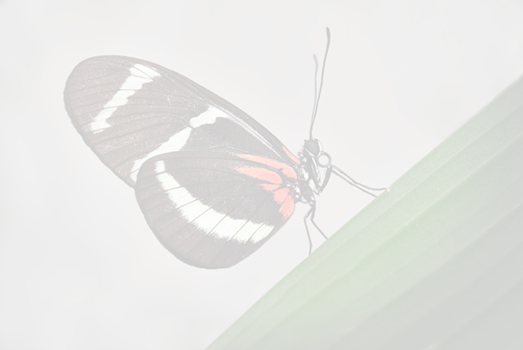
The image returned from the above code is shown below. Note that the image has high transparency because a small alpha value (50) is used.
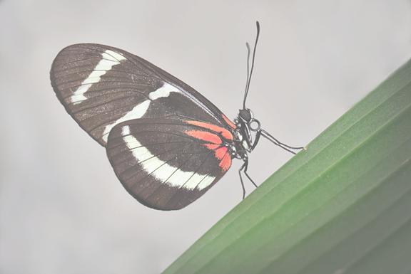
If the above code is changed to use a value of 160 for the alpha channel, the result will be less transparent, as shown below.
This section used the alpha channel for just a single image. We can also blend 2 images together using the alpha channel. We’ll look at how to do that in the following section.
Image Blending
This section adds 2 images together while using the alpha channel. The code for adding such images is listed below.
The 2 images are read in the 2 Mat arrays img and img2. These images have to be of equal size at the current time.
A third Mat is created named result to hold the result of the addition. To make this Mat of the same size as the previous 2 Mat arrays, it’s initially set equal to the first Mat img.
Mat img = Imgcodecs.imread("img.jpg");
Mat img2 = Imgcodecs.imread("img2.jpg");

Mat result = img;

for (int row = 0; row < img.rows(); row++) {
    for (int col = 0; col < img.cols(); col++) {
        double[] pixel1 = img.get(row, col);

        double[] pixel2 = img2.get(row, col);

        double alpha = 200.0;

        double fraction = alpha / 255.0;

        pixel1[0] = pixel1[0] * fraction + pixel2[0] * (1.0 - fraction);
        pixel1[1] = pixel1[1] * fraction + pixel2[1] * (1.0 - fraction);
        pixel1[2] = pixel1[2] * fraction + pixel2[2] * (1.0 - fraction);

        result.put(row, col, pixel1);
    }
}
Imgcodecs.imwrite("resultAlpha.jpg", result);
Using the 2 for loops, the current pixel is returned from the 2 Mat arrays. The used alpha value is set equal to 200, and then the fraction is calculated. After that, the new pixel is calculated by multiplying the fraction by the value returned from the first image, and the inverse of the fraction by the second image. The results of these multiplications are added together. The new pixel is then put into the result Mat. Finally, the image is saved.
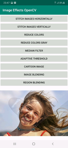
The saved image returned from the above code is shown below. Note that the first image appears stronger than the second image. The reason for this is that the fraction taken from the first image is 200/250=0.8, but just the fraction 0.2 is used with the second image. In other words, 80% of the pixels values in the result Mat are taken from the second image, and the remaining 20% are taken from the second Mat.
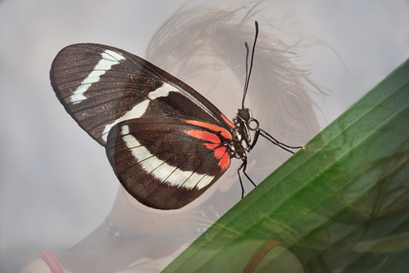
If the alpha value is made 50, then 80% of pixels values in the result Mat are taken from the second image and only 20% are from the second image. The result is shown below.
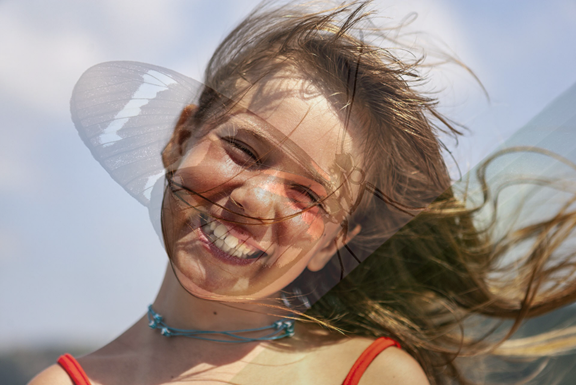
If the alpha is set to 0.0, then the result will be identical to the second image. If 255.0, then it will be identical to the first image.
This section blends 2 images together by blending each pixel. In the next section, we’ll look at blending a specific region from one image into another image.
Region Blending
Blending pixels from different images might have some undesirable effects, such as the one shown in the previous example where there’s an overlap between the 2 images.
Rather than blending the 2 images together, we can instead blend (i.e. copy) a specific region of one image into another image. It’s like removing the region from one image and then copying that region from the other image.
First, we need to highlight the region to be blended from the 2 images. This is done by creating a binary mask of size equal to the images to be blended. The mask is 255 for the pixels to be blended and 0 otherwise.
Using an image editing tool such as Photoshop, you can highlight the targeted region, as shown in the next figure. In this case, the butterfly region is highlighted in white. You don’t have to use white, but just use a color that can be distinguished from the other colors easily.
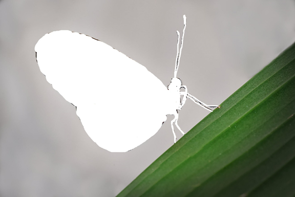
The above image is then converted into binary according to the code below. Note that there might be some noise in the result, which can be eliminated by editing the image again using Photoshop or any image editing tool. The binary image given below is then blended with the other image.
Mat imgBinary = Imgcodecs.imread("region.jpg");

Imgproc.cvtColor(imgBinary, imgBinary, Imgproc.COLOR_BGR2GRAY);
Imgproc.threshold(imgBinary, imgBinary, 200, 255.0, Imgproc.THRESH_BINARY);
Imgcodecs.imwrite("regionBinary.jpg", imgBinary);
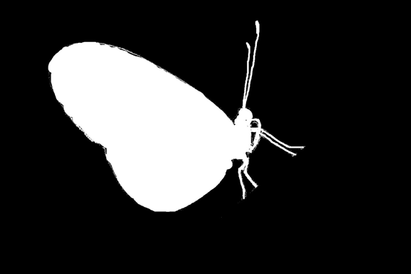
The binary image highlighted the region that will be blended. To blend such a region, the following code is used.
Mat img = Imgcodecs.imread("img1.jpg");
Mat img2 = Imgcodecs.imread("img2.jpg");
Mat imgBinary = Imgcodecs.imread("region.jpg");

Mat result = img2;

Imgproc.cvtColor(imgBinary, imgBinary, Imgproc.COLOR_BGR2GRAY);
Imgproc.threshold(imgBinary, imgBinary, 200, 255.0, Imgproc.THRESH_BINARY);
Imgcodecs.imwrite("regionBinary.jpg", imgBinary);

for (int row = 0; row < img.rows(); row++) {
    for (int col = 0; col < img.cols(); col++) {
        double[] img1Pixel = img.get(row, col);
        double[] binaryPixel = imgBinary.get(row, col);
        if (binaryPixel[0] == 255.0) {
            result.put(row, col, img1Pixel);
        }
    }
}
Imgcodecs.imwrite("binaryRegionBlend.jpg", imgBinary);
First, the img Mat holds the butterfly image, img2 holds the girl image, and imgBinary holds the region color image in which the butterfly was highlighted in white. The Mat result holds the final result. It’s set equal to img2.
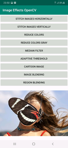
After that, the image in which the region highlighted is converted into binary. After that, the 2 for loops search for the white pixels with value 255.0 in the binary image. If a white pixel is found, then it indicates a butterfly pixel. This pixel is grabbed from the img Mat and put into the result Mat.
The result Mat is saved and is shown below. As you can see, the butterfly region is blended and nothing more.
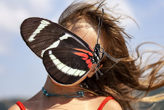
To automate this process, you’d need an object detector, which highlights the region to be blended.
Building the Android App
Let’s return to our Android project to see how we integrate this into our app. The activity XML layout of the main activity is listed below. Compared to the previous tutorial, there are just 2 more Button views for image and region blending.
The Button used for image blending calls the method imageBelnding() when clicked. The region blending Button calls the regionBelnding() method when clicked.
<?xml version="1.0" encoding="utf-8"?>
<LinearLayout xmlns:android="http://schemas.android.com/apk/res/android"
    xmlns:app="http://schemas.android.com/apk/res-auto"
    xmlns:tools="http://schemas.android.com/tools"
    android:layout_width="match_parent"
    android:layout_height="match_parent"
    android:orientation="vertical"
    tools:context=".MainActivity">

    <Button
        android:layout_width="match_parent"
        android:layout_height="wrap_content"
        android:id="@+id/stitchHorizontal"
        android:text="Stitch Images Horizontally"
        android:onClick="stitchHorizontal"/>
    <Button
        android:layout_width="match_parent"
        android:layout_height="wrap_content"
        android:id="@+id/stitchVertical"
        android:text="Stitch Images Vertically"
        android:onClick="stitchVectical"/>
    <Button
        android:layout_width="match_parent"
        android:layout_height="wrap_content"
        android:id="@+id/reduceColors"
        android:text="Reduce Colors"
        android:onClick="reduceImageColors"/>
    <Button
        android:layout_width="match_parent"
        android:layout_height="wrap_content"
        android:id="@+id/reduceColorsGray"
        android:text="Reduce Colors Gray"
        android:onClick="reduceImageColorsGray"/>
    <Button
        android:layout_width="match_parent"
        android:layout_height="wrap_content"
        android:id="@+id/medianFilter"
        android:text="Median Filter"
        android:onClick="medianFilter"/>
    <Button
        android:layout_width="match_parent"
        android:layout_height="wrap_content"
        android:id="@+id/adaptiveThreshold"
        android:text="Adaptive Threshold"
        android:onClick="adaptiveThreshold"/>
    <Button
        android:layout_width="match_parent"
        android:layout_height="wrap_content"
        android:id="@+id/cartoon"
        android:text="Cartoon Image"
        android:onClick="cartoonImage"/>
    <Button
        android:layout_width="match_parent"
        android:layout_height="wrap_content"
        android:id="@+id/transparency"
        android:text="Image Blending"
        android:onClick="blendImages"/>
    <Button
        android:layout_width="match_parent"
        android:layout_height="wrap_content"
        android:id="@+id/regionBlending"
        android:text="Region Blending"
        android:onClick="blendRegions"/>
    <ImageView
        android:layout_width="match_parent"
        android:layout_height="wrap_content"
        android:id="@+id/opencvImg"/>

</LinearLayout>
The application screen is shown below.
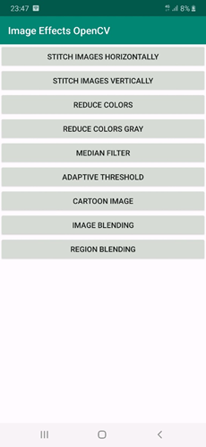
The MainActivity class is also edited to handle the blendImages() and blendRegions() methods, as mentioned below. Note that the images are available in the project as resources, which are loaded as Bitmap images. When such bitmap images are converted to OpenCV Mat arrays, the color space is BGRA.
Inside the blendImages() method, the method that does the actual image blending is called imageBlending(). Because the imageBlending() method accepts 2 Mat arrays with BGR color space, conversion is done before the imageBlending() method is called.
For region blending, the method that’s called inside the blendRegions() method is called regionBlending(). In addition to the 2 arguments received by the imageBlending() method, the regionBlending() method accepts a third Mat representing the binary mask.
package com.example.imageeffectsopencv;

import android.graphics.Bitmap;
import android.graphics.BitmapFactory;
import android.media.MediaScannerConnection;
import android.net.Uri;
import android.os.Bundle;
import android.os.Environment;
import android.support.v7.app.AppCompatActivity;
import android.util.Log;
import android.view.View;
import android.widget.ImageView;

import com.example.imageeffectsopencv.R;

import org.opencv.android.OpenCVLoader;
import org.opencv.android.Utils;
import org.opencv.core.Core;
import org.opencv.core.Mat;
import org.opencv.core.Size;
import org.opencv.imgproc.Imgproc;

import java.io.File;
import java.io.FileOutputStream;
import java.text.SimpleDateFormat;
import java.util.ArrayList;
import java.util.Arrays;
import java.util.Date;
import java.util.List;
import java.util.Locale;

import static org.opencv.core.Core.LUT;
import static org.opencv.core.CvType.CV_8UC1;

public class MainActivity extends AppCompatActivity {

    @Override
    protected void onCreate(Bundle savedInstanceState) {
        super.onCreate(savedInstanceState);
        setContentView(R.layout.activity_main);
        OpenCVLoader.initDebug();
    }

    public void blendRegions(View view){
        BitmapFactory.Options options = new BitmapFactory.Options();
        options.inScaled = false; // Leaving it to true enlarges the decoded image size.
        Bitmap img1Bitmap = BitmapFactory.decodeResource(getResources(), R.drawable.im1, options);
        Bitmap img2Bitmap = BitmapFactory.decodeResource(getResources(), R.drawable.im2, options);
        Bitmap img1MaskBitmap = BitmapFactory.decodeResource(getResources(), R.drawable.mask_im1, options);

        Mat img1 = new Mat();
        Mat img2 = new Mat();
        Mat img1Mask = new Mat();

        Utils.bitmapToMat(img1Bitmap, img1);
        Imgproc.cvtColor(img1, img1, Imgproc.COLOR_BGRA2BGR);

        Utils.bitmapToMat(img2Bitmap, img2);
        Imgproc.cvtColor(img2, img2, Imgproc.COLOR_BGRA2BGR);

        Utils.bitmapToMat(img1MaskBitmap, img1Mask);
        Imgproc.cvtColor(img1Mask, img1Mask, Imgproc.COLOR_BGRA2BGR);
        Imgproc.cvtColor(img1Mask, img1Mask, Imgproc.COLOR_BGR2GRAY);
        Imgproc.threshold(img1Mask, img1Mask, 200, 255.0, Imgproc.THRESH_BINARY);

        Mat result = regionBlending(img1, img2, img1Mask);

        Bitmap imgBitmap = Bitmap.createBitmap(result.cols(), result.rows(), Bitmap.Config.ARGB_8888);
        Utils.matToBitmap(result, imgBitmap);

        ImageView imageView = findViewById(R.id.opencvImg);
        imageView.setImageBitmap(imgBitmap);
        saveBitmap(imgBitmap, "region_blending");
    }

    public void blendImages(View view){
        BitmapFactory.Options options = new BitmapFactory.Options();
        options.inScaled = false; // Leaving it to true enlarges the decoded image size.
        Bitmap img1Bitmap = BitmapFactory.decodeResource(getResources(), R.drawable.im1, options);
        Bitmap img2Bitmap = BitmapFactory.decodeResource(getResources(), R.drawable.im2, options);

        Mat img1 = new Mat();
        Mat img2 = new Mat();
        Utils.bitmapToMat(img1Bitmap, img1);
        Imgproc.cvtColor(img1, img1, Imgproc.COLOR_BGRA2BGR);
        Utils.bitmapToMat(img2Bitmap, img2);
        Imgproc.cvtColor(img2, img2, Imgproc.COLOR_BGRA2BGR);

        Mat result = imageBlending(img1, img2);

        Bitmap imgBitmap = Bitmap.createBitmap(result.cols(), result.rows(), Bitmap.Config.ARGB_8888);
        Utils.matToBitmap(result, imgBitmap);

        ImageView imageView = findViewById(R.id.opencvImg);
        imageView.setImageBitmap(imgBitmap);
        saveBitmap(imgBitmap, "image_blending");
    }

    public void cartoonImage(View view) {
        BitmapFactory.Options options = new BitmapFactory.Options();
        options.inScaled = false; // Leaving it to true enlarges the decoded image size.
        Bitmap original = BitmapFactory.decodeResource(getResources(), R.drawable.part3, options);

        Mat img1 = new Mat();
        Utils.bitmapToMat(original, img1);
        Imgproc.cvtColor(img1, img1, Imgproc.COLOR_BGRA2BGR);

        Mat result = cartoon(img1, 80, 15, 10);

        Bitmap imgBitmap = Bitmap.createBitmap(result.cols(), result.rows(), Bitmap.Config.ARGB_8888);
        Utils.matToBitmap(result, imgBitmap);

        ImageView imageView = findViewById(R.id.opencvImg);
        imageView.setImageBitmap(imgBitmap);
        saveBitmap(imgBitmap, "cartoon");
    }

    public void reduceImageColors(View view){
        BitmapFactory.Options options = new BitmapFactory.Options();
        options.inScaled = false; // Leaving it to true enlarges the decoded image size.
        Bitmap original = BitmapFactory.decodeResource(getResources(), R.drawable.part3, options);

        Mat img1 = new Mat();
        Utils.bitmapToMat(original, img1);

        Mat result = reduceColors(img1, 80, 15, 10);

        Bitmap imgBitmap = Bitmap.createBitmap(result.cols(), result.rows(), Bitmap.Config.ARGB_8888);
        Utils.matToBitmap(result, imgBitmap);

        ImageView imageView = findViewById(R.id.opencvImg);
        imageView.setImageBitmap(imgBitmap);
        saveBitmap(imgBitmap, "reduce_colors");
    }

    public void reduceImageColorsGray(View view){
        BitmapFactory.Options options = new BitmapFactory.Options();
        options.inScaled = false; // Leaving it to true enlarges the decoded image size.
        Bitmap original = BitmapFactory.decodeResource(getResources(), R.drawable.part3, options);

        Mat img1 = new Mat();
        Utils.bitmapToMat(original, img1);

        Imgproc.cvtColor(img1, img1, Imgproc.COLOR_BGR2GRAY);
        Mat result = reduceColorsGray(img1, 5);

        Bitmap imgBitmap = Bitmap.createBitmap(result.cols(), result.rows(), Bitmap.Config.ARGB_8888);
        Utils.matToBitmap(result, imgBitmap);

        ImageView imageView = findViewById(R.id.opencvImg);
        imageView.setImageBitmap(imgBitmap);
        saveBitmap(imgBitmap, "reduce_colors_gray");
    }

    public void medianFilter(View view) {
        BitmapFactory.Options options = new BitmapFactory.Options();
        options.inScaled = false; // Leaving it to true enlarges the decoded image size.
        Bitmap original = BitmapFactory.decodeResource(getResources(), R.drawable.part3, options);

        Mat img1 = new Mat();
        Utils.bitmapToMat(original, img1);
        Mat medianFilter = new Mat();
        Imgproc.cvtColor(img1, medianFilter, Imgproc.COLOR_BGR2GRAY);

        Imgproc.medianBlur(medianFilter, medianFilter, 15);

        Bitmap imgBitmap = Bitmap.createBitmap(medianFilter.cols(), medianFilter.rows(), Bitmap.Config.ARGB_8888);
        Utils.matToBitmap(medianFilter, imgBitmap);

        ImageView imageView = findViewById(R.id.opencvImg);
        imageView.setImageBitmap(imgBitmap);
        saveBitmap(imgBitmap, "median_filter");
    }

    public void adaptiveThreshold(View view) {
        BitmapFactory.Options options = new BitmapFactory.Options();
        options.inScaled = false; // Leaving it to true enlarges the decoded image size.
        Bitmap original = BitmapFactory.decodeResource(getResources(), R.drawable.part3, options);

        Mat adaptiveTh = new Mat();
        Utils.bitmapToMat(original, adaptiveTh);
        Imgproc.cvtColor(adaptiveTh, adaptiveTh, Imgproc.COLOR_BGR2GRAY);

        Imgproc.medianBlur(adaptiveTh, adaptiveTh, 15);

        Imgproc.adaptiveThreshold(adaptiveTh, adaptiveTh, 255, Imgproc.ADAPTIVE_THRESH_MEAN_C, Imgproc.THRESH_BINARY, 9, 2);

        Bitmap imgBitmap = Bitmap.createBitmap(adaptiveTh.cols(), adaptiveTh.rows(), Bitmap.Config.ARGB_8888);
        Utils.matToBitmap(adaptiveTh, imgBitmap);

        ImageView imageView = findViewById(R.id.opencvImg);
        imageView.setImageBitmap(imgBitmap);
        saveBitmap(imgBitmap, "adaptive_threshold");
    }

    public void stitchVectical(View view){
        BitmapFactory.Options options = new BitmapFactory.Options();
        options.inScaled = false; // Leaving it to true enlarges the decoded image size.
        Bitmap im1 = BitmapFactory.decodeResource(getResources(), R.drawable.part1, options);
        Bitmap im2 = BitmapFactory.decodeResource(getResources(), R.drawable.part2, options);
        Bitmap im3 = BitmapFactory.decodeResource(getResources(), R.drawable.part3, options);

        Mat img1 = new Mat();
        Mat img2 = new Mat();
        Mat img3 = new Mat();
        Utils.bitmapToMat(im1, img1);
        Utils.bitmapToMat(im2, img2);
        Utils.bitmapToMat(im3, img3);

        Bitmap imgBitmap = stitchImagesVectical(Arrays.asList(img1, img2, img3));
        ImageView imageView = findViewById(R.id.opencvImg);
        imageView.setImageBitmap(imgBitmap);
        saveBitmap(imgBitmap, "stitch_vectical");
    }

    public void stitchHorizontal(View view){
        BitmapFactory.Options options = new BitmapFactory.Options();
        options.inScaled = false; // Leaving it to true enlarges the decoded image size.
        Bitmap im1 = BitmapFactory.decodeResource(getResources(), R.drawable.part1, options);
        Bitmap im2 = BitmapFactory.decodeResource(getResources(), R.drawable.part2, options);
        Bitmap im3 = BitmapFactory.decodeResource(getResources(), R.drawable.part3, options);

        Mat img1 = new Mat();
        Mat img2 = new Mat();
        Mat img3 = new Mat();
        Utils.bitmapToMat(im1, img1);
        Utils.bitmapToMat(im2, img2);
        Utils.bitmapToMat(im3, img3);

        Bitmap imgBitmap = stitchImagesHorizontal(Arrays.asList(img1, img2, img3));
        ImageView imageView = findViewById(R.id.opencvImg);
        imageView.setImageBitmap(imgBitmap);
        saveBitmap(imgBitmap, "stitch_horizontal");
    }

    Mat regionBlending(Mat img, Mat img2, Mat mask) {
        Mat result = img2;

        for (int row = 0; row < img.rows(); row++) {
            for (int col = 0; col < img.cols(); col++) {
                double[] img1Pixel = img.get(row, col);
                double[] binaryPixel = mask.get(row, col);
                if (binaryPixel[0] == 255.0) {
                    result.put(row, col, img1Pixel);
                }
            }
        }
        return result;
    }

    Mat imageBlending(Mat img, Mat img2) {
        Mat result = img;

        for (int row = 0; row < img.rows(); row++) {
            for (int col = 0; col < img.cols(); col++) {
                double[] pixel1 = img.get(row, col);

                double[] pixel2 = img2.get(row, col);

                double alpha = 30.0;

                double fraction = alpha / 255.0;

                pixel1[0] = pixel1[0] * fraction + pixel2[0] * (1.0 - fraction);
                pixel1[1] = pixel1[1] * fraction + pixel2[1] * (1.0 - fraction);
                pixel1[2] = pixel1[2] * fraction + pixel2[2] * (1.0 - fraction);

                result.put(row, col, pixel1);
            }
        }
        return result;
    }

    Mat cartoon(Mat img, int numRed, int numGreen, int numBlue) {
        Mat reducedColorImage = reduceColors(img, numRed, numGreen, numBlue);

        Mat result = new Mat();
        Imgproc.cvtColor(img, result, Imgproc.COLOR_BGR2GRAY);
        Imgproc.medianBlur(result, result, 15);

        Imgproc.adaptiveThreshold(result, result, 255, Imgproc.ADAPTIVE_THRESH_MEAN_C, Imgproc.THRESH_BINARY, 15, 2);

        Imgproc.cvtColor(result, result, Imgproc.COLOR_GRAY2BGR);

        Log.d("PPP", result.height() + " " + result.width() + " " + reducedColorImage.type() + " " + result.channels());
        Log.d("PPP", reducedColorImage.height() + " " + reducedColorImage.width() + " " + reducedColorImage.type() + " " + reducedColorImage.channels());

        Core.bitwise_and(reducedColorImage, result, result);

        return result;
    }

    Mat reduceColors(Mat img, int numRed, int numGreen, int numBlue) {
        Mat redLUT = createLUT(numRed);
        Mat greenLUT = createLUT(numGreen);
        Mat blueLUT = createLUT(numBlue);

        List<Mat> BGR = new ArrayList<>(3);
        Core.split(img, BGR); // splits the image into its channels in the List of Mat arrays.

        LUT(BGR.get(0), blueLUT, BGR.get(0));
        LUT(BGR.get(1), greenLUT, BGR.get(1));
        LUT(BGR.get(2), redLUT, BGR.get(2));

        Core.merge(BGR, img);

        return img;
    }

    Mat reduceColorsGray(Mat img, int numColors) {
        Mat LUT = createLUT(numColors);

        LUT(img, LUT, img);

        return img;
    }

    Mat createLUT(int numColors) {
        // When numColors=1 the LUT will only have 1 color which is black.
        if (numColors < 0 || numColors > 256) {
            System.out.println("Invalid Number of Colors. It must be between 0 and 256 inclusive.");
            return null;
        }

        Mat lookupTable = Mat.zeros(new Size(1, 256), CV_8UC1);

        int startIdx = 0;
        for (int x = 0; x < 256; x += 256.0 / numColors) {
            lookupTable.put(x, 0, x);

            for (int y = startIdx; y < x; y++) {
                if (lookupTable.get(y, 0)[0] == 0) {
                    lookupTable.put(y, 0, lookupTable.get(x, 0));
                }
            }
            startIdx = x;
        }
        return lookupTable;
    }

    Bitmap stitchImagesVectical(List<Mat> src) {
        Mat dst = new Mat();
        Core.vconcat(src, dst); //Core.hconcat(src, dst);
        Bitmap imgBitmap = Bitmap.createBitmap(dst.cols(), dst.rows(), Bitmap.Config.ARGB_8888);
        Utils.matToBitmap(dst, imgBitmap);

        return imgBitmap;
    }

    Bitmap stitchImagesHorizontal(List<Mat> src) {
        Mat dst = new Mat();
        Core.hconcat(src, dst); //Core.vconcat(src, dst);
        Bitmap imgBitmap = Bitmap.createBitmap(dst.cols(), dst.rows(), Bitmap.Config.ARGB_8888);
        Utils.matToBitmap(dst, imgBitmap);

        return imgBitmap;
    }

    public void saveBitmap(Bitmap imgBitmap, String fileNameOpening){
        SimpleDateFormat formatter = new SimpleDateFormat("yyyy_MM_dd_HH_mm_ss", Locale.US);
        Date now = new Date();
        String fileName = fileNameOpening + "_" + formatter.format(now) + ".jpg";

        FileOutputStream outStream;
        try{
            // Get a public path on the device storage for saving the file. Note that the word external does not mean the file is saved in the SD card. It is still saved in the internal storage.
            File path = Environment.getExternalStoragePublicDirectory(Environment.DIRECTORY_PICTURES);

            // Creates directory for saving the image.
            File saveDir =  new File(path + "/HeartBeat/");

            // If the directory is not created, create it.
            if(!saveDir.exists())
                saveDir.mkdirs();

            // Create the image file within the directory.
            File fileDir =  new File(saveDir, fileName); // Creates the file.

            // Write into the image file by the BitMap content.
            outStream = new FileOutputStream(fileDir);
            imgBitmap.compress(Bitmap.CompressFormat.JPEG, 100, outStream);

            MediaScannerConnection.scanFile(this.getApplicationContext(),
                    new String[] { fileDir.toString() }, null,
                    new MediaScannerConnection.OnScanCompletedListener() {
                        public void onScanCompleted(String path, Uri uri) {
                        }
                    });

            // Close the output stream.
            outStream.close();
        }catch(Exception e){
            e.printStackTrace();
        }
    }
}
After clicking the “Image Blending” button:
And for the “Region Blending” button:
Conclusion
This tutorial discussed building an Android app for blending images. At first, the alpha channel is discussed for supporting transparency in color images.
OpenCV supports adding an alpha channel to the color spaces using the cvtColor() method. The alpha channel is added to just a single image. After that, all pixels in 2 images are blended together. To avoid overlapping between the pixels from the different images, one region in an image is copied to another image.
At this point, the Android app has 2 limitations, which are:
- The user cannot select images to apply effects to—just the resource images packaged within the app can be used.
- For effects working with multiple images, all images must be of the same size.
- There is no space for adding buttons for new effects.
The next tutorial will solve these limitations.

Comments 0 Responses